C.A.T.S. Software
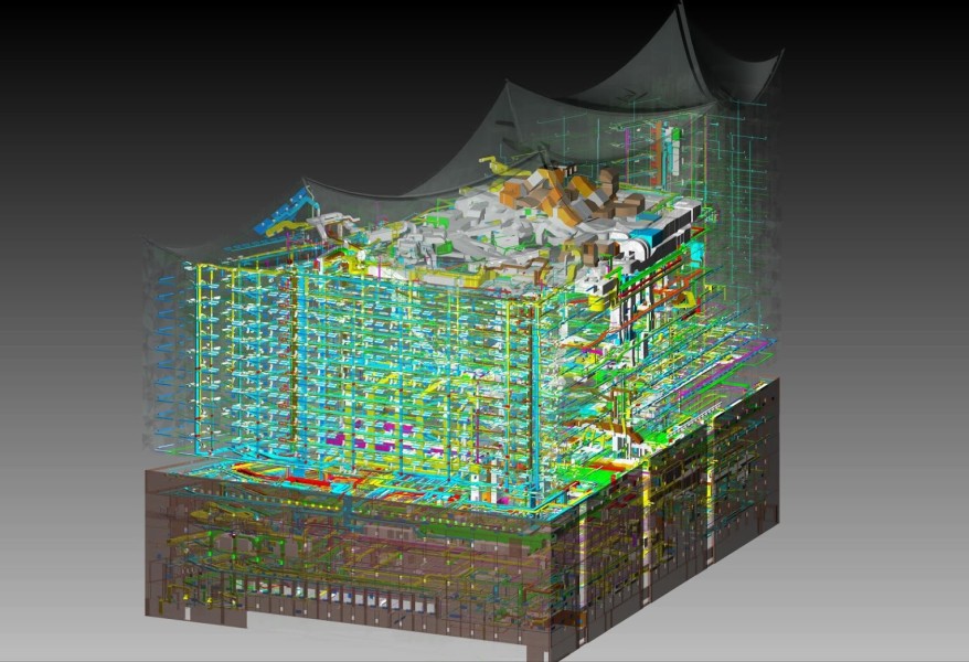
C.A.T.S. Software provides you with state of the art 3D planning and construction. Our integrated calculations sets our solution apart from competitors worldwide.
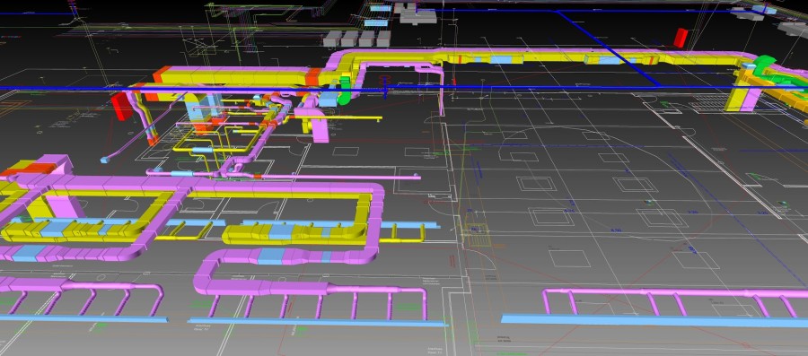
- Ventilation
- Piping
- Sprinkler
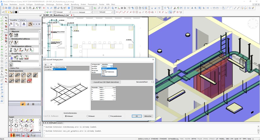
- Electro 3D Construction
- with integrated calculation, IFC enabled
Description
Ventilation Professional This CAE program represents a huge increase in productivity for the user: Using the construction line, engineering bureaus can develop a 3D plan extremely quickly and simply during the planning phase. Applying a process of fitting and joining, planners and contractors can make precise constructions in 3D, followed by automatic calculation of duct surface and pressure loss. Overview of Functions for Planners and Constructors -Generation of drawing, assembly and as-built drawings -Automatic generation of isometric and section views even in 2D -Realistic 2D and 3D display of duct system -Flexible layer management with freely selectable layer names -3D libraries for components, air outlets, fittings (circular or quadrilateral), and fire protection -Pilot for comfortable placement of structural elements and components -Multi-adapter to allow all possible combinations of fittings -Automatic display of duct shadow in every view -Display of duct insulation and insulation thickness -Fully automatic duct generation using the construction line and existing boundary conditions -Variable specification of maximum air speed, maximum duct height, etc. -Assistant for calculating cross-sections, speeds, volume flows, equivalent diameters, etc. -Rapid redimensioning of individual parts -Retrospective setting of components and fittings -Retrospective assignment of attributes, such as material, insulation, etc. -Automatic generation of 3D links, manual or automatic angle input -Associative dimensioning and labelling in model and ground plan area -Automatic flange dimensioning, information signs, height indications, offset texts, etc. -Comfortable tool tips for all components, display of dimensions, angles, etc. -Automatic and/or manual issuing of item numbers -Module-universal collision test Piping Construction The Piping Construction module is used for constructing pipelines or complete systems for use in heating, plumbing systems or sprinklers in 3D. Each drawn component is displayed realistically. Comprehensive product catalogues from well-known manufacturers are incorporated. Any choice of cross-section can be generated automatically from a drawing. Overview of Functions: -Construction using fitting/joining or as a single line trace, as required -Display with or without insulation, as required - insulations can be displayed in silhouette -All components are neutral as regards manufacturer -Armatures can be installed in existing pipes -Automatic creation of adapter pieces -All component measurements and labels can be changed -Security enquiries and warning messages in the event of non-possible connections -Item numbers issued automatically or manually -Dimensioning in inches, DN, or diameter, with or without wall thickness -User-defined information signs -Automatic generation of cross-sections and views -View-sensitive pipe shadow and central lines -Automatic pipe installation between two building components -Inclusion of necessary connectors, such as sockets, nipples or clamps -Various drawing aids, such as automatic gradient, etc. -Automatic 3D offset -Module-universal collision testing Sprinkler Overview of functions -Generation of drawing, assembly and as-built drawings -Automatic generation of isometric and section views -2D library with access to more than 100 graphical symbols -2D recesses for slits and openings -Flexible management of added storey plans -Editable databases for all components, including transfer of defined symbols -Automatic placement of sprinklers in accordance with VdS rules -Pipelines displayed as single lines, in analogy with AutoCAD Line command -Fully automatic generation of branch lines -Optional conversion of lines, circles, etc. to sprinkler objects -Editing functions for individual components or for complete pipe system -Generation of angle branch-offs and automatic pipe branch connection Calculations: -With approval of the society of non-life insurances -Calculation method as per Hazen-Williams and Darcy-Weisbach -Calculation of e.g. foaming agents -Calculation as per NFBA 13 -Calculation as per British Standard BS 9251 -Editable databasefor all components -Tabular inputting of sprinklers, components and pipelines -Automatic reading of all data from the drawing, such as bends, branches etc. -Choice of calculation in terms of pressure at least effective sprinkler, feed point, or water impingement -Reports as per VdS format available in Ascii or Excel. C.A.T.S Electrical Overview of functions -3D raceway for trays, ladders and baskets -user definable parts -hange systems automatic coordinated to the raceway -Control cabinets and other installation equipment -User-defined clearances for the practical and standardized clash detection tests -toolset for quantity take-offs, labeling and drawing creation -IFC exports for BIM-projects --------- Our HVAC Software is IFC enabled!


BricsCAD Pro V18
Windows